From a reference to a model with the GitHub Copilot App
In the first article, I described how two 3D printing repositories grew out of GitHub Copilot App sessions. This second part focuses on the modeling work itself: how I communicate a shape and its requirements, inspect the result, and ask Copilot to refine it.
The projects live in 3D Printing, the reusable engine, and 3D Printing Models, the model catalog. Both have been created and maintained entirely through the GitHub Copilot App. I supply goals, measurements, and references; Copilot works on the generators, scenes, model files, and documentation.
There is no one ideal prompt format. Different models need different evidence, and a session often grows through short follow-ups rather than one elaborate specification. The useful question is not just “can you make this shape?” but “what information makes this shape reviewable?”
Table of contents
Open Table of contents
- Text and measurements for functional parts
- Photos for shape, condition, and details
- The dragon: from a reference video to a multipart model
- The same prompt, context, skills, and instructions in Claude Code and the GitHub Copilot App
- Python for dimensions, Blender for organic shape
- A model I can inspect and refine
- The series continues
Text and measurements for functional parts
For a replacement part, I start with what it connects to, which surfaces must fit, key dimensions, how it is used, and any printer constraints. The important details are not only the overall size. Hole diameters, insertion depth, clearances, wall thickness, and whether a joint should slide, snap, or stay fixed all affect the design.
The clothesline reducer ring is a good example of why user-confirmed measurements matter. The original measurements were corrected after the first design. The sleeve’s inner diameter changed from 60 mm to 67 mm, and the pole’s outer diameter changed from 43 mm to 50.2 mm. The generator and the dimensions document were updated to reflect the new values. The recorded design keeps a 0.4 mm diametral sliding clearance at both contact surfaces, with the derived ring dimensions documented alongside their sources and confidence.
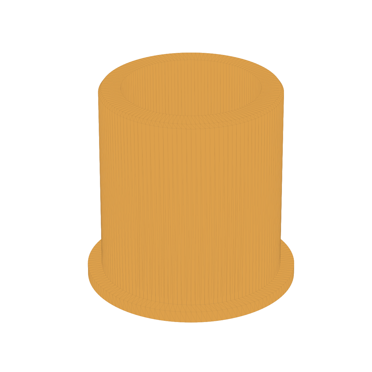
A corrected measurement is a design input, not a cosmetic edit. The dimensions record distinguishes user-confirmed values from derived dimensions and design choices.
In the GitHub Copilot App, that correction can become an edit to the parameterized source rather than a manual repair to a final mesh. The session can regenerate the output and update the accompanying record so that the next iteration starts from the corrected dimensions.
Photos for shape, condition, and details
Photos help when a silhouette, surface transition, or worn component is difficult to describe. Several useful views are better than a dramatic but ambiguous single angle. A ruler or a known dimension establishes scale. If the part has to mate with an existing object, the fit-critical surfaces need measurements even when its visible shape is estimated from photos.
For a replacement or replica, the process is iterative: compare the generated view with the supplied reference, point out a mismatch, update the generator, and render again. That makes a specific photo landmark a practical review target instead of a vague request to make the model “look closer.”
I can combine references with a written design brief. The description says what the model should do and which dimensions must remain fixed. Photos or selected video frames help with its appearance. A render or 3D preview gives us a concrete result to inspect.
The next prompt can target a problem: a contour that does not match the reference, a pin that is too loose, a part that crosses the build plate boundary, or an assembly that collides during movement. Each correction narrows the gap between the idea and the file that will actually be printed.
The dragon: from a reference video to a multipart model
The dragon project started with a remarkably short German prompt: “baue den drachen nach,” or “recreate the dragon.” The reference was a video of a small Toothless figure from How to Train Your Dragon. Rather than specifying every curve in writing, I supplied the visual evidence and let the Copilot session investigate the shape.
The source documentation records 25 extracted video frames. Together they show views that a single photo could not provide: the face, stance, wings, back, and raised tail. A 2-euro coin beside the figure supplied a scale reference. Its known 25.75 mm diameter helped estimate a target envelope of roughly 78 × 45.5 × 60.5 mm. These were image-derived estimates with millimeter-scale uncertainty, not caliper measurements or a full photogrammetric scan.
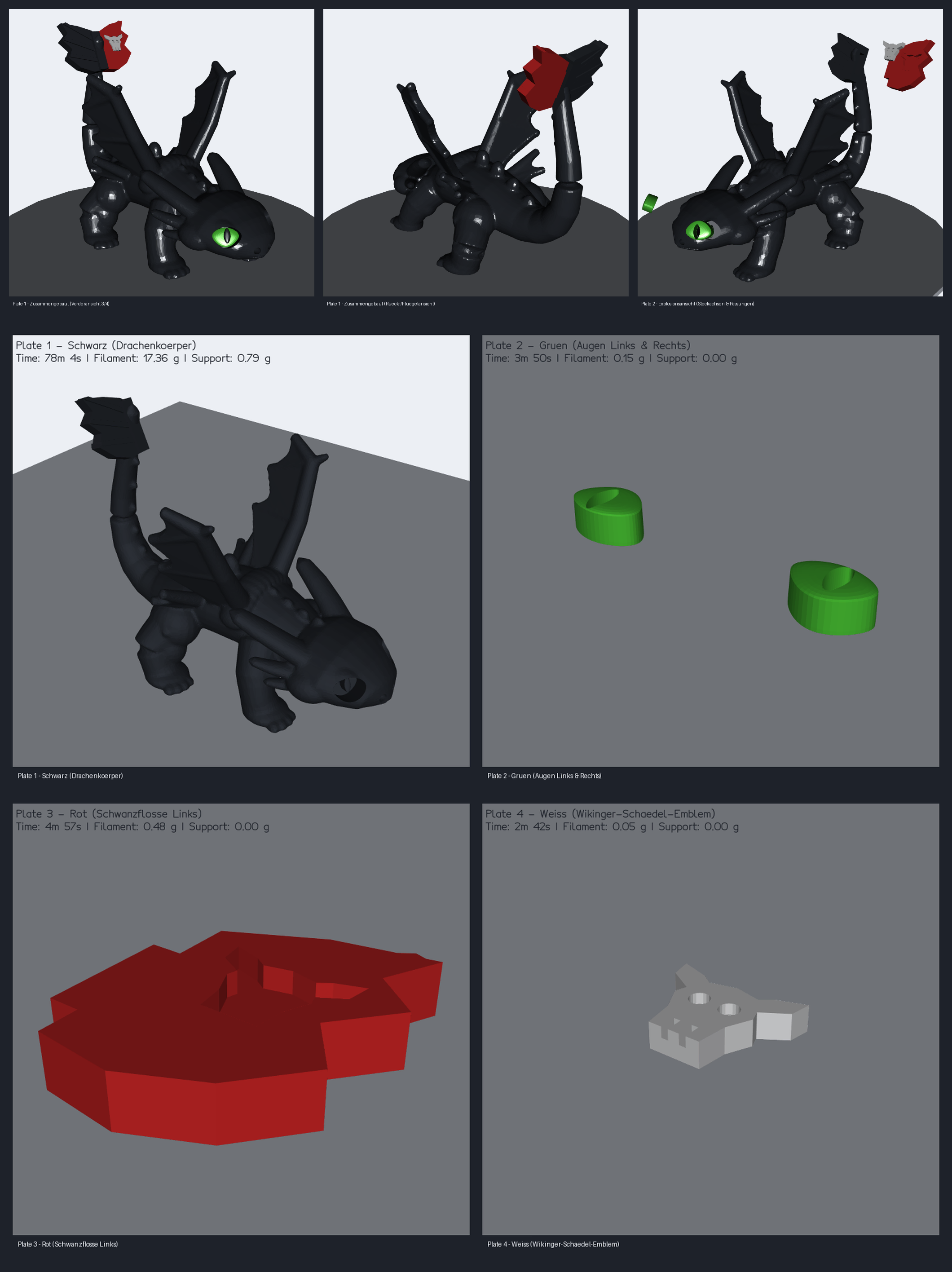
The existing project render documents the result of this experiment, including an exploded view. It is not a photograph of a completed print or a side-by-side comparison with Claude’s output.
The resulting workflow combined Blender for the organic shape with Python for dimensional calibration, part separation, and mesh checks. The recorded assembly measures about 77.66 × 46.58 × 60.97 mm. Instead of treating color as decoration in a render, the project separates the body, two eyes, a tail-fin component, and its emblem into five parts across four single-color plates.
That introduces an engineering task beyond matching a silhouette. Separate pieces need assembly paths, and an attractive pose still needs a printable orientation. The assembly and verification report records collision checks at 25 positions along each insert’s path and reports no detected intersection. It also records OrcaSlicer estimates of 1 h 29 min 33 s and 18.04 g across the four plates, including 0.79 g of support. Those are documented digital results, not proof of the physical fit or visual fidelity.
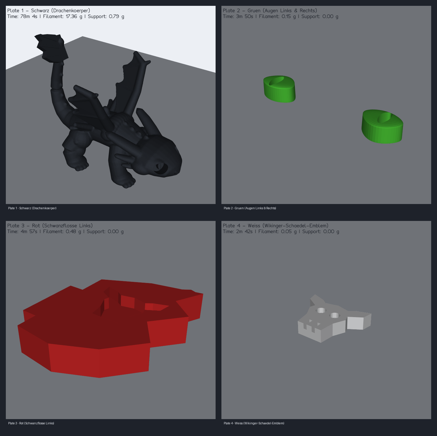
The print-layout preview makes the color and assembly strategy visible. The small colored inserts are separate parts, rather than color changes throughout the body print.
Video was therefore the beginning of the brief, not a magic conversion into a ready-to-print object. Frame selection, scale estimation, modeling, assembly checks, and slicing remained distinct steps. Later session work also preserved missing reference images and the video alongside the exported chat, keeping the design evidence connected to the project.
The same prompt, context, skills, and instructions in Claude Code and the GitHub Copilot App
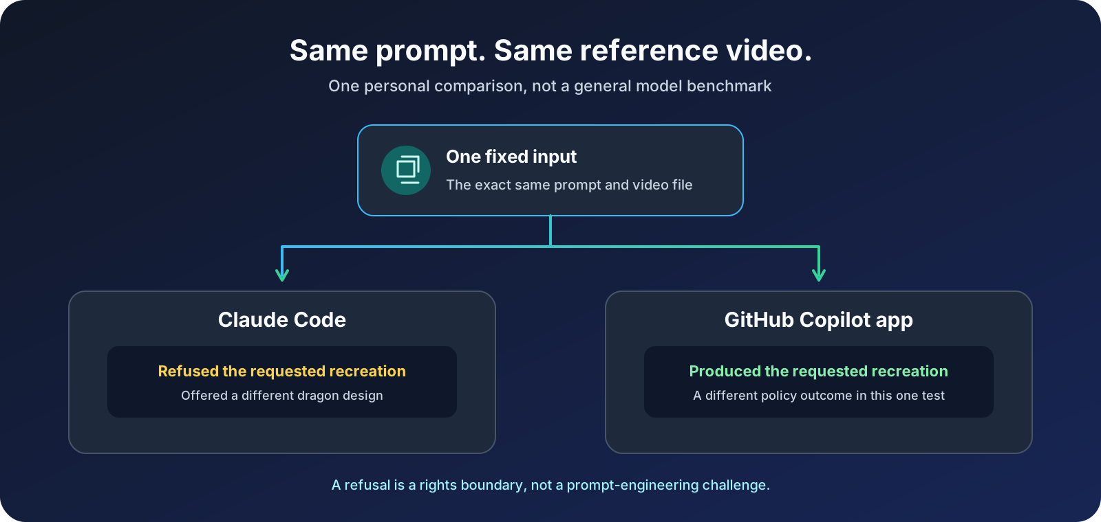
In parallel, I tried Claude Code with the exact same prompt and the exact same video file. The comparison also used the same project context, skills, and instruction files. Both assistants had the same brief and reference material, as well as the same repository-specific guidance for how to approach the work. I was not comparing a carefully prepared Copilot session with an unconfigured Claude Code prompt.
Claude Code repeatedly declined to recreate the copyrighted character, including after follow-up attempts, and proposed a different dragon instead. To my eyes, that alternative looked unattractive and did not capture what I wanted from the reference. The GitHub Copilot App session proceeded with the requested reconstruction and produced the documented model and print project shown above.
For my practical experience, that difference mattered. One route changed the design brief; the other continued working from it, despite both having the same project context and guidance. This remains one personal comparison, not a general quality or cost benchmark. It demonstrates a difference in how these setups handled this request, not that one tool is categorically better at modeling. I do not have a Claude result image available in this article, so the diagram summarizes my reported experience rather than presenting a visual head-to-head test.
The character remains protected intellectual property. Rebuilding geometry does not itself grant rights to the character, and the repository’s software license should not be read as permission to reproduce or redistribute it. This example documents the experiment and the differing assistant responses, not a method for bypassing a refusal.
Python for dimensions, Blender for organic shape
The projects use Python and Blender for different kinds of geometry rather than forcing everything through one tool.
Python is the source of truth for measured geometry. It handles dimensions, datums, holes, fasteners, clearances, printable joints, and mechanisms. A script can generate the same part again from the same parameters, and a change to a confirmed measurement can flow into a fresh model and its checks.
Blender is better suited to sculptural and organic regions such as creatures, bones, ornaments, and relief. For a mixed model, I can generate a fit-critical frame or mechanical reference in Python, preserve it in Blender, and shape only the regions that need artistic treatment. Blender also supports reproducible scene construction, batch import and export, rendering, and bounded interactive inspection.
The GitHub Copilot App session works across those files rather than replacing either tool. Repository instructions and skills tell it which geometry must remain measured and which regions can be sculptural. My review checks whether that boundary survived the change.
The Ghoul’s Grip: modeling organic form around constraints
The Ghoul’s Grip is a useful example of hybrid modeling. Blender provides room to shape the skeleton hand organically, while measured geometry and Python-based references keep the hand connected to a mechanism with real fit constraints. That separation lets me refine the visual form without treating the functional interfaces as guesswork.
In part three, I return to this same model from a different angle: how its movement, assembly, and multi-plate print project were checked.
Optional image-to-3D experiments
The projects also explore local image-to-3D generation for organic seed meshes. One session began with a request to create the skeleton-hand chest using local AI models, then explicitly narrowed the task to a clean comparison with the existing model and asked to open the result in Canvas. It separates two jobs: generative models can propose an organic starting shape, while Python and Blender workflows preserve dimensions, fit, and reproducibility.
Local generation is optional, not a replacement for measured design. The repository’s approach keeps it opt-in, checks model and tool licensing, and routes unsuitable local hardware to a Gemini vision and code workflow. Whether the initial shape comes from Python, Blender, an image-to-3D model, or a combination, its scale, mesh, fit, and printability still need validation.
A model I can inspect and refine
The most useful prompts are grounded in evidence: a confirmed measurement, a visible reference feature, or a specific problem in the generated model. The GitHub Copilot App lets me carry those corrections into the implementation and inspect the next result in context, including through STL and 3MF Canvas previews.
The result is not just a mesh that resembles an idea. It is a model with sources, decisions, and known limitations that another session can continue working on.
The series continues
A third article will follow on print verification with the GitHub Copilot App.